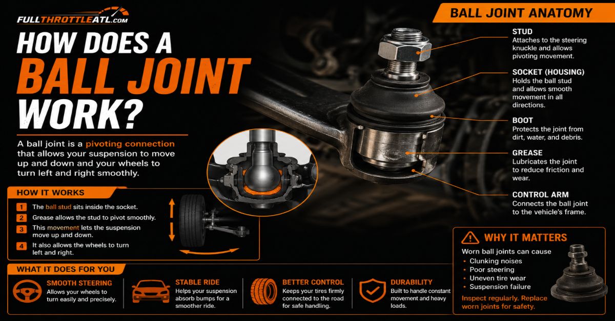
Understanding how a ball joint works is essential for maintaining vehicle safety, and replacing a worn unit restores tight steering response and eliminates dangerous suspension clunks. This comprehensive guide covers the mechanical principles of the joint and walks you through a precise 7-step replacement process taking 2 to 3.5 hours per side at a moderate difficulty level, with success depending entirely on proper press alignment and strict torque discipline.
Before You Start
- Time Required: 2 to 3.5 hours per side
- Difficulty Level: Intermediate to Advanced
- Estimated Cost: 50 to 150 dollars for parts and specialty tool rentals
- Prerequisite Skills: Basic suspension teardown, torque wrench usage, and safe jack stand placement
- Required Tools & Materials Checklist:
- New ball joint kit (joint, castle nut, cotter pin, grease zerk, snap ring)
- Ball joint press kit with C-clamp and adapter cups
- Hydraulic floor jack and heavy-duty jack stands (rated for vehicle weight)
- Torque wrench (capable of 30 to 150 ft-lbs)
- Socket set and wrenches (14mm to 24mm) plus a lug nut socket
- 1/2-inch drive breaker bar
- Pickle fork or ball joint separator tool
- Heavy ball-peen hammer or small sledgehammer
- Chassis grease and grease gun
- Wire brush, brake cleaner, and safety glasses
How a Ball Joint Works
The mechanism mirrors a human hip joint, functioning as the primary flexible pivot point in a modern vehicle suspension system.
- Pivot Action: A highly polished steel ball stud is permanently seated inside a lubricated steel or polyurethane housing socket, enclosed by a protective rubber boot that keeps out dirt and moisture.
- Multi-Axis Movement: As the vehicle travels over uneven road surfaces, the ball rotates and pivots within the housing socket. This dual action allows the wheel assembly to move vertically to absorb road impacts while simultaneously turning horizontally for steering control.
- Load Bearing: The joint constantly transfers the heavy weight of the vehicle chassis down to the wheel assembly, while also enduring high lateral forces generated during cornering and braking.
Step-by-Step Ball Joint Replacement Process
Step 1: Vehicle Setup, Wheel Removal, and Safety Chocking
Park the vehicle on a flat, solid concrete surface, engage the parking brake firmly, and place wheel chocks behind the rear tires. Loosen the front wheel lug nuts by one complete turn using your lug wrench. Position your hydraulic floor jack under the manufacturer approved front jacking point, lift the vehicle, and lower it securely onto heavy-duty jack stands. Remove the loosened lug nuts completely and take off the front wheel to expose the suspension assembly.
- Success Check: The vehicle sits completely stable on the jack stands with zero front-to-back or side-to-side rock when pushed firmly by hand.
- Common Mistake: Placing jack stands on thin sheet metal pinch welds without a slotted rubber adapter, which can crush the frame rail.
Step 2: Disassembling Steering and Brake Components
Unbolt the brake caliper mounting bolts using the correct metric socket, lift the caliper off the rotor, and secure it safely to the coil spring or frame using a bungee cord or metal hook. Slide the brake rotor straight off the wheel hub and set it aside. If the steering knuckle lacks clearance for the upcoming press work, unbolt the outer tie rod end from the knuckle using an open-end wrench and a socket.
- Success Check: The brake caliper hangs securely without any tension, twist, or sharp bend on the rubber brake hydraulic hose.
- Common Mistake: Letting the brake caliper dangle by its flexible rubber hose, which induces internal stress and causes hidden brake line ruptures.
Step 3: Separating the Tapered Ball Joint Stud
Locate the old ball joint at the bottom of the steering knuckle, remove the old split cotter pin from the castle nut, and discard it. Back off the castle nut until it sits flush with the top of the threaded stud to protect the threads from hammer damage. Wedge a pickle fork or mechanical ball joint separator tool between the control arm and the steering knuckle. Strike the side of the knuckle casting firmly with a heavy hammer to shock the tapered stud loose. Once the taper breaks free, remove the castle nut entirely and pivot the steering knuckle out of the way.
- Success Check: The steering knuckle separates cleanly from the control arm stud, allowing the knuckle to swing freely away from your workspace.
- Common Mistake: Hammering directly downward onto the threaded ball stud itself, which mushrooms the threads and makes nut removal impossible.
Step 4: Pressing Out the Old Ball Joint
Inspect the control arm for a metal retaining snap ring; if present, remove it using heavy-duty snap ring pliers. Clean away decades of road grime, rust, and scale around the ball joint flange using a wire brush and a spray of brake cleaner. Assemble the C-clamp press kit over the control arm, placing a large receiving cup on the bottom side of the arm to catch the falling joint and a pushing adapter disc on top of the joint housing. Turn the press drive screw clockwise using a 1/2-inch breaker bar until the old ball joint presses completely out of the control arm housing.
- Success Check: The old ball joint drops out into the bottom receiving cup, leaving a clean circular bore hole in the control arm.
- Common Mistake: Forcing the press tool when it binds, which can slip and shatter the C-clamp frame if the adapter cups are not seated flat.
Step 5: Pressing In the New Ball Joint
Thoroughly clean the interior walls of the control arm receiving hole with a wire brush to remove any residual rust or burrs. Align the new ball joint so it enters the hole perfectly straight and perpendicular to the arm surface. Reverse your press configuration by placing the receiving cup on top of the control arm and the flat installer adapter directly against the bottom flange of the new joint. Turn the drive screw clockwise with your breaker bar until the new joint seats completely flush against the control arm face. Install the new metal snap ring firmly into its designated groove around the joint housing.
- Success Check: The snap ring clicks fully into its groove with zero gaps, and a feeler gauge cannot slip between the joint flange and the control arm.
- Common Mistake: Pressing the new joint in at a slight angle, which shaves metal off the control arm hole and ruins the component.
Step 6: Reassembling the Knuckle and Torqueing to Specification
Swing the steering knuckle back into position and guide the new tapered ball joint stud up through the mounting hole in the knuckle. Thread the new castle nut onto the stud by hand to catch the threads. If the tapered stud begins to spin in place as you turn the nut, place your floor jack under the bottom of the ball joint housing and raise it slightly to apply upward pressure, which locks the taper. Use a calibrated torque wrench to tighten the castle nut to your vehicle specification, typically between 50 and 80 ft-lbs. Check the alignment of the cotter pin hole; if the hole does not align with the slots in the nut, tighten the nut slightly further until it aligns. Never loosen the nut to achieve alignment. Insert the new cotter pin through the hole and bend both legs outward flat against the sides of the nut.
- Success Check: The castle nut reaches factory torque, the cotter pin passes through the slot cleanly with its legs secured flat, and zero play exists in the joint.
- Common Mistake: Loosening a torqued castle nut to make the cotter pin hole line up, which leaves the fastener under-torqued and vulnerable to fatigue failure.
Step 7: Final Greasing and System Reassembly
Thread the included metal grease zerk fitting into the port on the new ball joint and snug it gently with a small wrench. Attach a grease gun filled with high-quality chassis grease to the zerk fitting and pump grease slowly into the joint until the rubber dust boot expands slightly. Reinstall the brake rotor flat against the wheel hub, remount the brake caliper over the rotor, and torque the caliper mounting bolts to manufacturer specifications. Mount the wheel back onto the wheel studs, hand-tighten the lug nuts, lower the vehicle to the ground, and finish by torqueing the lug nuts in a star pattern to 80 to 100 ft-lbs.
- Success Check: The rubber boot is plump and filled with grease without bursting its seams, and all brake components are securely torqued.
- Common Mistake: Overfilling the rubber boot with grease until it pops or ruptures, which allows immediate contamination by road water and grit.
Common Mistakes and How to Fix Them
- Joint Spins During Tightening: The tapered stud rotates inside the steering knuckle hole instead of tightening. Fix: Place a hydraulic jack under the bottom of the ball joint housing and lift slightly to force the taper to seat.
- Control Arm Deformation During Pressing: The C-clamp frame tilts because the adapter cup is resting on the lip of the control arm. Fix: Stop immediately, reposition the adapter so it contacts only the structural rim of the joint flange, and restart.
- Misaligned Cotter Pin Hole: The castle nut reaches proper torque, but the hole is hidden behind a solid section of the nut. Fix: Tighten the nut slightly more until the next slot aligns. Never back the nut off.
- Damaged Rubber Boot: The installer tool or a rogue screwdriver nicks the rubber boot during assembly. Fix: Replace the rubber boot immediately with a matching aftermarket boot before driving, or road salt will destroy the internal bearings within weeks.
Variations and Alternative Tools
- Bolted versus Pressed Joints: Many modern trucks and SUVs feature bolt-in ball joints rather than press-in types. For bolted styles, you simply remove three heavy mounting bolts instead of using a C-clamp press kit.
- Using an Air Impact Wrench: If a manual breaker bar proves too difficult against heavily rusted press-in joints, you can drive the C-clamp press screw using a cordless high-torque impact wrench, provided you wear heavy eye protection and monitor frame alignment constantly.
- Torch Assistance for Severe Rust: When a joint refuses to budge under maximum C-clamp pressure, heating the outside of the control arm ring with a propane or acetylene torch for 60 seconds causes the metal to expand slightly, releasing the grip on the joint housing.
Time and Cost Breakdown
- Time Investment: Expect 2 to 3.5 hours for your first side, and roughly 1.5 to 2 hours for the second side once you have mastered the tool setup.
- Financial Cost: DIY parts and tool rentals total 50 to 150 dollars. Professional mechanic labor shops typically charge between 350 and 600 dollars per side for parts and labor combined.
Frequently Asked Questions
How do I know if my ball joints are actually bad?
Symptoms include a loud metallic clunking or popping noise when driving over bumps or turning the steering wheel at low speeds. You can verify failure by jacking up the front end, grabbing the top and bottom of the tire, and shaking it firmly; any noticeable play or looseness indicates a worn ball joint.
Can I drive with a failing ball joint?
Driving with a severely worn ball joint is extremely dangerous because a complete structural separation causes the wheel to collapse inward, leading to an immediate loss of vehicle control and a severe accident. Replace worn joints at the first sign of excessive play.
Do I need a wheel alignment after replacement?
Yes, replacing a ball joint disturbs the precise geometry of the front suspension and steering linkage. You should schedule a professional four-wheel alignment immediately following any suspension repair to prevent rapid tire wear and steering pull.
Should I replace both ball joints at the same time?
While you can replace only the failed side if you are operating on a strict budget, mechanics recommend replacing ball joints in pairs (both driver and passenger sides). Suspension components experience similar wear rates, meaning the opposite side is likely close to failure if one has already worn out.