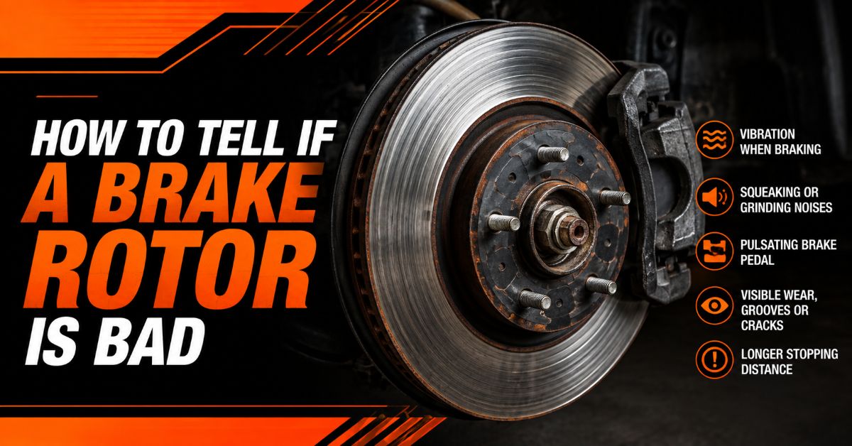
Learning how to tell if a brake rotor is bad involves performing a road symptom test, inspecting the disc surface for scoring and heat spots, and taking precision measurements for minimum thickness and lateral runout. By completing this 5-step diagnostic process in 60 to 90 minutes, you can pinpoint warped or worn rotors using basic hand tools, a digital micrometer, and a dial indicator.
Before You Start
- Total Time Required: 60–90 minutes for a set of two wheels
- Difficulty Level: Beginner to Intermediate
- Estimated Cost: $0 (DIY inspection) or $30–$50 for basic precision measuring tools
- Prerequisite Knowledge: Ability to safely jack up a vehicle, remove wheels, and read precision instruments (micrometer/dial gauge).
Required Tools & Materials Checklist:
- Floor jack (rated for vehicle weight) and two jack stands
- Lug wrench or breaker bar (1/2-inch drive)
- Wheel chocks (2)
- Digital micrometer or deep-throat brake caliper ($0–25\text{ mm} / 0–1\text{ in}$ range)
- Dial indicator with flexible arm and magnetic or mechanical clamp base
- Brake cleaner spray (1 aerosol can) and wire brush
- Two oversized washers or oversized nuts (for clamping rotor against hub)
- Clean shop rags or microfiber towels
- Vehicle factory service specifications (minimum discard thickness stamped on rotor)
Diagnostic Steps: Inspecting Brake Rotors
Step 1: Perform the Road and Noise Diagnostic Test
Conduct a controlled road test to determine whether your braking symptoms stem from front rotors, rear rotors, or unrelated suspension issues.
Drive the vehicle on a clear, flat road at $40\text{ mph}$ ($65\text{ km/h}$) and apply light to moderate brake pressure. If the steering wheel shakes in your hands, the issue is almost always in the front brake rotors. If the steering wheel remains still but you feel a rhythmic pulsation through the brake pedal or seat frame, the issue is in the rear brake rotors.
- Success Checkpoint: You will know you have isolated the issue when you can trigger the pulsation exclusively while pressing the brake pedal (if it shakes at speed without touching the brakes, your tires are out of balance).
- Common Mistake: Confusing ABS activation with rotor warpage. ABS creates a rapid, mechanical chatter in slick conditions; warped rotors create a smooth, speed-proportional wobble during normal dry braking.
Step 2: Safely Lift the Vehicle and Expose the Brake Rotor
Raise the vehicle off the ground, stabilize it on jack stands, and remove the wheel assembly to expose the rotor face.
Park on level concrete, engage the parking brake, and place chocks in front of and behind the tires on the unlifted axle. Loosen the lug nuts $1/2$ turn counterclockwise using a breaker bar while the tires are firmly on the ground. Position your floor jack beneath the manufacturer’s designated frame jack point, lift the vehicle, and insert jack stands directly underneath structural frame rails before lowering the full weight onto the stands. Fully unbolt the lug nuts and pull the wheel straight off.
- Success Checkpoint: You will know it worked when the vehicle rests completely stationary on jack stands and the brake rotor and caliper assembly are fully accessible.
- Common Mistake: Raising the vehicle without cracking the lug nuts first. Attempting to loosen tight lug nuts while the car is elevated on a jack causes dangerous vehicle instability.
Step 3: Perform Visual and Physical Surface Inspection
Clean the friction surface thoroughly and examine both sides of the disc for physical stress marks, scoring, and structural breakdown.
Spray the rotor face on both sides with aerosol brake cleaner and scrub heavy brake dust and loose rust using a stiff wire brush. Wipe dry with a shop towel. Inspect the outer sweep area and inner face for deep concentric grooves (scoring). Feel the outer edge of the rotor for a pronounced raised lip where the brake pads stop contact. Examine the metal surface for dark blue/purple thermal spots or spiderweb-like hairline cracks around cooling vents and stud holes.
- Success Checkpoint: You will know it worked when the bare metal of the rotor is clean, dry, and visible under direct light.
- Common Mistake: Inspecting only the outer face of the rotor. Inner rotor faces often rust and score significantly faster than outer faces due to sticking caliper slider pins.
Step 4: Measure Minimum Thickness and Disc Thickness Variation
Take precision thickness measurements across multiple points on the rotor disc using a digital micrometer to check against factory minimum specs.
Locate the minimum discard thickness spec (e.g., "MIN THICK 24.0mm") stamped directly onto the rotor hub edge or back face. Calibrate your digital micrometer to zero. Slide the anvil of the micrometer past the outer rust lip, measuring approximately $10\text{ mm}$ ($1/4\text{ inch}$) inward from the outer edge into the smooth brake pad sweep path. Measure and record the thickness at $8$ evenly spaced points around the circumference of the disc. Subtraction yields Disc Thickness Variation:
$$\text{DTV} = \text{Maximum Measured Thickness} – \text{Minimum Measured Thickness}$$
Sample Calculation:
Point 1: 24.45 mm
Point 2: 24.42 mm
Point 3: 24.46 mm
Point 4: 24.41 mm
---------------------------------------------
Max Reading: 24.46 mm  |  Min Reading: 24.41 mm
DTV = 24.46 mm - 24.41 mm = 0.05 mm (DISCARD)
Max allowable DTV limit is 0.013 mm (0.0005 in).
- Success Checkpoint: You will know it worked when you have 8 recorded numbers and an calculated DTV value to compare against your vehicle’s stamped spec.
- Common Mistake: Restively clamping the micrometer flat over the outer rust lip. The lip sits higher than the worn friction surface and gives a false, excessively thick reading.
Step 5: Measure Lateral Runout with a Dial Indicator
Clamp the rotor tightly against the wheel hub and measure side-to-side wobble using a dial indicator during a manual $360^{\circ}$ rotation.
Thread two lug nuts onto the wheel studs upside down (flat side facing the rotor) over large washers to lock the rotor completely flat against the hub flange. Clamp the magnetic or mechanical base of your dial indicator to a rigid suspension component (like the strut body or steering knuckle). Position the indicator plunger perpendicular to the rotor face, $10\text{ mm}$ inward from the outer edge. Push the gauge in until the needle moves slightly (pre-loading it), then zero the outer bezel. Rotate the rotor by hand through one full $360^{\circ}$ turn and note the total sweep of the needle (Total Indicator Reading).
Lateral Runout (TIR) Limit Check:
- Dial Needle Sweep Range: 0.00 mm to 0.08 mm
- Maximum Allowed Runout: 0.05 mm (0.002 in)
- Result: Exceeds specification by 0.03 mm -> Replace Rotor
- Success Checkpoint: You will know it worked when the rotor turns smoothly without shifting on the studs and the dial needle moves predictably across a defined range.
- Common Mistake: Measuring lateral runout without tightening lug nuts against the rotor face. A loose rotor sits crooked on the hub studs, producing massive false runout readings.
1.Road Test:Isolate front vs. rear vibration.
Apply brakes at 40 mph; felt in steering wheel = front rotors, felt in pedal/seat = rear rotors.
2.Lift & Surface Prep:Expose clean rotor faces.
Crack lug nuts, elevate vehicle on jack stands, remove wheel, and scrub rotor faces clean with brake cleaner and wire brush.
3.Micrometer Thickness Test:Check 8 points for wear & DTV.
Measure thickness at 8 points 10mm from outer edge. If any reading is below stamped MIN THICK or DTV exceeds 0.013 mm, discard.
4.Dial Indicator Runout Test:Check for side-to-side wobble.
Lug-clamp rotor to hub face. Mount dial indicator perpendicular to surface, zero gauge, and rotate 360°. Runout must remain below 0.05 mm.
Common Mistakes and How to Fix Them
| Error Made | Why It Causes False Diagnostics | How to Correct / Fix It |
| Measuring over the outer edge lip | Outer edge rust lip is un-worn; misleads you into thinking a thin rotor is still within spec. | Reach micrometer anvil $10\text{ mm}$ ($1/4\text{ in}$) past the lip into the active pad sweep path. |
| Measuring runout on a dirty hub | Rust scale caught between hub flange and rotor back forces rotor to sit at an angle. | Remove rotor retention screws, remove rotor, and scrub hub face with a wire brush or hub cleaning disc before testing. |
| Ignoring Disc Thickness Variation (DTV) | A rotor can meet minimum overall thickness but still pulse if thickness varies around the circle. | Calculate Max minus Min reading across 8 points. If variance exceeds $0.013\text{ mm}$ ($0.0005\text{ in}$), replace/machine disc. |
| Skipping rotor clamping nuts | Spinning an un-clamped rotor creates artificial wobble relative to stud clearance gaps. | Tighten 2–3 lug nuts inverted with flat washers to $30\text{ ft-lbs}$ of torque before mounting dial indicator. |
| Replacing only one damaged rotor | Imbalances braking force left-to-right, pulling vehicle during emergency stops. | Always install new rotors and brake pad sets in axle pairs (both fronts or both rears together). |
Technical Process Variations
Variation A: Measuring Rotors Without Removing the Caliper
If you lack the socket sets to unbolt caliper brackets, you can perform a basic inspection through the wheel spokes or caliper inspection window.
- Use a deep-throat brake micrometer designed with curved anvils that clear caliper body obstacles.
- Inspect outer visual conditions and check minimum thickness at accessible openings.
- Constraint: You cannot measure full $360^{\circ}$ lateral runout or inspect the hidden inner friction face using this shortcut.
Variation B: Checking Rotors With Captive Hub Assemblies
Some older trucks and classic rear-wheel-drive vehicles integrate the rotor directly with the wheel hub bearing assembly.
- Do not remove stud nuts to isolate the rotor face.
- Place the dial indicator plunger directly on the rotor’s back friction surface while mounted to spindle shaft.
- Adjust allowable lateral runout tolerance upwards slightly to $0.07\text{ mm}$ ($0.003\text{ in}$) to account for total spindle bearing endplay.
Repair Costs and Time Projections
| Path | Required Parts / Services | Estimated DIY Cost | Estimated Shop Cost |
| Inspection Only | Brake Cleaner, Shop Towels | $5 – $10 | $60 – $120 (Diagnostic Fee) |
| Resurfacing (Machining) | Bench Lathe Turning Service (Per Pair) | $30 – $60 | $150 – $250 |
| Full Rotor Replacement | 2 New Rotors + New Pad Set (Front or Rear) | $80 – $220 | $350 – $650 |
Frequently Asked Questions
Can I resurface (turn) my rotors instead of replacing them?
Yes, provided the rotor thickness remains above the stamped minimum discard thickness after lathe resurfacing. A machinist removes roughly $0.5\text{ mm}$ to $1.0\text{ mm}$ of metal during turning. If taking off metal drops the disc below its stamped minimum spec, turning is unsafe and replacement is mandatory.
Why do rotors get dark blue or purple spots?
Blue or purple discolored spots indicate severe localized overheating (often exceeding $1,200^{\circ}\text{F}$ / $650^{\circ}\text{C}$). This thermal stress alters the iron’s crystal structure into hard spots called cementite. Cementite spots do not wear down evenly with the rest of the iron, causing irreversible pedal vibration.
How many miles do brake rotors typically last?
Standard brake rotors generally last between 30,000 and 70,000 miles (48,000 to 112,000 km). Lifespan varies heavily based on driving style, brake pad friction compound (semi-metallic pads wear rotors faster than ceramic pads), towing habits, and exposure to road salt or moisture.
Can bad rotors damage my vehicle’s suspension?
Yes. Driving continuously on severely warped rotors creates persistent high-frequency vibrations during braking. Over time, these cyclic shocks degrade lower control arm bushings, tie rod ends, wheel bearings, and front strut mounts, leading to premature steering component failure and uneven tire wear.