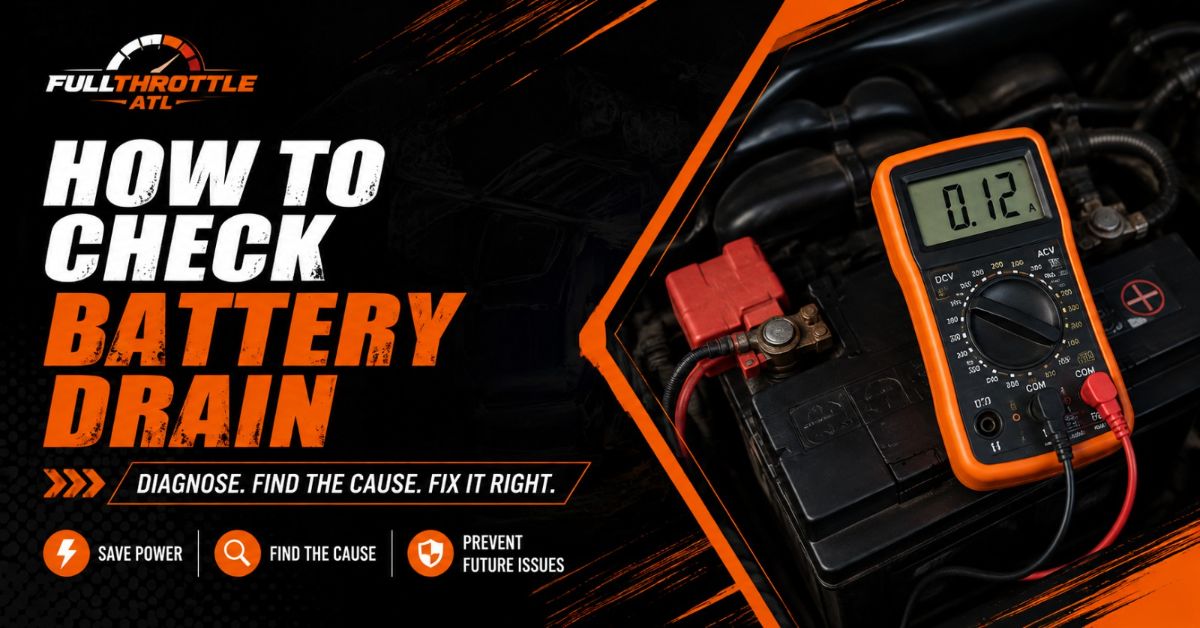
A parasitic battery drain occurs when electrical components continue pulling current from your vehicle’s battery after the ignition is turned off and the control modules have gone to sleep. Standard parasitic draw on modern vehicles ranges from 20mA to 50mA (0.02A to 0.05A) to power keyless entry receivers, clock memories, and engine control units (ECUs). Any steady draw exceeding 50mA will drain a healthy battery within 24 to 72 hours.
To learn how to check battery drain accurately, you will complete a 6-step diagnostic process using a digital multimeter placed in series with the negative battery cable. This guide details the exact setup, sleep-mode preparation, measurement criteria, and circuit isolation methods required to pinpoint the source of power loss on the first attempt.
Before You Start
| Parameter | Specification / Requirement |
| Estimated Time | 45–90 minutes (includes module sleep wait time) |
| Skill Level | Beginner to Intermediate |
| Typical Cost | $0 (if you own a DMM) or $15–$35 for basic tools |
| Required Tools | Digital Multimeter (10A/20A fused port, 1mA resolution), Socket Wrench Set (8mm, 10mm, 13mm), 12-inch Jumper Wire with Alligator Clips, Flathead Screwdriver, Plastic Fuse Puller |
| Safety Gear | Eye protection (ANSI Z87.1 approved) and nitrile or mechanics gloves |
| Prerequisites | Vehicle battery must be fully charged (minimum 12.6V static voltage) |
Step-by-Step Guide to Checking Battery Drain
1.Step 1: Verify Battery Health and Charge Level:Prerequisite voltage check.
Test static battery voltage with a multimeter across the posts before conducting any amperage testing. Switch your multimeter to DC Volts ($V\mathrel{=}$), place the red probe on the positive terminal, and the black probe on the negative terminal. A healthy, fully charged 12V lead-acid battery must read between 12.6V and 12.8V.
If the reading is below 12.4V, charge the battery with a smart charger before proceeding. Testing parasitic draw on a discharged or degraded battery yields false readings because dropping system voltage triggers vehicle computer modules to wake up periodically.
- Success Checkpoint: Your multimeter displays a steady voltage reading of at least 12.6V with the ignition off.
- Common Mistake: Attempting a parasitic draw test on a flat battery ($<12.0\text{V}$). This causes modules to cycle endlessly, masking the true source of the drain.
2.Step 2: Prepare Vehicle and Bypass Latch Switches:Simulate closed doors and hood.
Park the vehicle in a quiet work area, switch off all interior lights, climate control systems, and accessory switches, and remove the key from the ignition. Open the hood and any doors needed to access interior fuse panels. Using a flathead screwdriver or blunt rod, manually push the hood latch and door latch mechanisms inward until they click twice into their fully locked positions.
Tripping the latches fools the Body Control Module (BCM) into registering that all doors and hoods are closed, enabling full electronic sleep mode while leaving fuse panels exposed. Move all smart key fobs at least 20 feet (6 meters) away from the vehicle during the entire test.
- Success Checkpoint: Dashboard door-ajar indicators turn off, and dome lights shut down completely.
- Common Mistake: Leaving key fobs on the workbench nearby. Proximity fobs continuously ping the vehicle’s keyless entry module, keeping the CAN-bus network awake and drawing 300mA to 800mA.
3.Step 3: Configure the Digital Multimeter:Correct probe jack and scale settings.
Insert the black probe lead into the COM (Common) jack on your digital multimeter. Move the red probe lead from the standard voltage/ohms jack into the high-current 10A or 20A fused jack. Turn the selector dial to the DC Amperes setting ($A$ or $A\mathrel{=}$).
Do not select the milliamps ($\text{mA}$) setting at this stage; initial power connection spikes will immediately blow the fragile 200mA/400mA internal fuse inside your meter.
- Success Checkpoint: Red probe is firmly seated in the high-amp jack, and the display indicates
0.00 Aor0.000 ADC. - Common Mistake: Leaving the red lead in the $V/\Omega$ port while measuring current. Connecting a voltage-configured meter in series creates a direct short circuit, instantly blowing the meter fuse or damaging internal traces.
4.Step 4: Connect the Multimeter in Series via Jumper Bridge:Maintain continuous power supply.
Loosen the 10mm or 8mm retaining nut on the negative battery terminal cable, but leave the clamp seated on the post. Attach one alligator clip of your jumper wire to the negative battery post and the other clip to the metal lug of the negative terminal cable. Now, lift the terminal clamp off the battery post while maintaining the jumper connection.
Next, press the multimeter’s red probe against the disconnected negative cable clamp and the black probe against the negative battery post. Once both probes make firm contact, unclip the jumper wire. Electrical current now flows seamlessly through the multimeter without interrupting power to the vehicle modules.
- Success Checkpoint: The meter displays a live amperage reading without the car clock, radio, or alarm resetting.
- Common Mistake: Breaking electrical contact during clamp removal without a jumper wire bridge. Complete power loss resets all onboard computers, forcing you to restart the 60-minute sleep cycle countdown.
5.Step 5: Allow Vehicle Modules to Sleep and Read Baseline Draw:Wait for current stabilization.
Secure the meter probes in place using screw clamps or locking alligator clips, then leave the vehicle undisturbed for 30 to 60 minutes. Modern luxury vehicles and cars equipped with multiple CAN-bus networks require up to an hour for every control node to transition into low-power sleep mode.
After the wait period, check the digital display. A standard, acceptable baseline reading is between 0.020A and 0.050A (20mA to 50mA). Any reading consistently equal to or greater than 0.100A (100mA) confirms an active parasitic battery drain.
- Success Checkpoint: Amperage reading drops and stabilizes below 0.050A (50mA).
- Common Mistake: Taking a reading after only 5 minutes. Engine control modules, telematics systems, and security units frequently perform routine diagnostic sweeps for 15–30 minutes after key-off.
6.Step 6: Isolate the Faulty Circuit via Fuse Diagnostics:Locate the failing branch component.
If total draw exceeds 0.050A, open the under-hood or interior fuse box. Using a plastic fuse puller, remove individual blade fuses one by one while monitoring the multimeter display. If the amperage reading does not change after pulling a fuse, reinstall it into its original slot before moving to the next one.
When you remove a fuse and the current drops immediately into the acceptable range ($<50\text{mA}$), you have identified the isolated circuit. Cross-reference the fuse designation number on the fuse box lid or in your vehicle owner’s manual to identify all electrical components powered by that specific circuit.
- Success Checkpoint: Amperage display drops sharply from high draw down to normal baseline range ($0.020\text{A}$–$0.050\text{A}$) upon removing a single fuse.
- Common Mistake: Pulling multiple fuses simultaneously. Removing multiple fuses makes it impossible to identify which single circuit was responsible for the load.
Alternative Isolation Method: Voltage Drop Test Across Fuses
Pulling fuses on vehicles manufactured after 2005 can sometimes wake up resting CAN-bus modules, leading to inaccurate diagnostic results. Professional technicians prefer testing millivolt ($\text{mV}$) drop across the top test points of blade fuses without removing them.
       [ Fuse Test Probe Point A ]      [ Fuse Test Probe Point B ]
                    │                                │
                    ▼                                ▼
              ┌───────────┐                    ┌───────────┐
              │  Metal    │ ─── Fuse Element── │  Metal    │
              │  Exposed  │   (Internal Res)   │  Exposed  │
              └───────────┘                    └───────────┘
- Set Meter to Millivolts: Turn your multimeter dial to DC Millivolts ($\text{mV}\mathrel{=}$) and keep the red probe in the standard $V/\Omega$ port.
- Touch Probe Tips: Place the sharp probe tips onto the two exposed metal test pads on the back of each blade fuse while it remains installed in the fuse block.
- Interpret the Reading:
- A inactive circuit carrying $0\text{mA}$ current shows 0.0 mV.
- An active circuit carrying current produces a small millivolt reading (typically 0.1 mV to 5.0 mV) due to electrical resistance across the fuse element.
- Convert Millivolts to Milliamps: Use standard Automotive Fuse Voltage Drop Charts (matching fuse rating and type: Mini, Standard, Maxi) to translate millivolts directly into actual current draw in milliamps.
Common Mistakes and How to Fix Them
1. Blown Multimeter Internal Fuse
- Failure Mode: The multimeter displays
0.00 Aconstantly, even when electrical accessories (like headlights) are activated. - Cause: The probe was connected in series while current exceeded 10A (e.g., turning on the ignition or opening a door), blowing the internal glass/ceramic fuse.
- Fix: Switch the multimeter to continuity/resistance mode ($\Omega$). Touch the red probe to the COM port and the black probe to the 10A port. If the meter displays
OL(Open Loop) or infinite resistance, the fuse is blown. Unscrew the meter back housing and replace the internal 10A 600V fast-acting ceramic fuse.
2. Accidental ECU Wake-Up During Testing
- Failure Mode: Current drops to 30mA, but suddenly spikes to 1.5A while pulling fuses.
- Cause: Jostling a door pin switch, moving the key fob too close, or pulling a fuse on a shared communication bus node.
- Fix: Reinsert the pulled fuse immediately. Reset your timer and allow the vehicle to sit undisturbed for 20 minutes until modules re-enter sleep mode before continuing.
3. High Draw Originating from Unfused Circuits
- Failure Mode: Every single fuse in both under-hood and interior fuse boxes has been pulled, but current draw remains above 200mA.
- Cause: The parasitic load stems from an unfused component connected directly to the battery distribution block, most commonly a shorted internal rectifier diode inside the alternator, or a stuck starter solenoid.
- Fix: Disconnect the primary $B+$ battery output cable attached to the back of the alternator (ensure the battery negative terminal is unhooked first to avoid sparks). Re-test series amperage draw. If current drops under 50mA, replace the alternator assembly.
Variations: Testing Different Vehicle Types and Equipment
Testing with an Inductive DC Current Clamp
For quick non-intrusive diagnostics without disconnecting battery terminals:
- Tool Requirement: Low-current DC amp clamp capable of measuring resolution down to $1\text{mA}$ (0.001A). Note: standard AC-only clamps will not work on automotive DC circuits.
- Process: Clamp the jaw around the single negative battery ground cable. Zero the clamp before reading.
- Advantage: Completely eliminates the risk of resetting computer modules or blowing multimeter fuses.
Testing Vehicles with Dual-Battery Systems
- Process: Trucks and diesel vehicles equipped with dual auxiliary batteries require disconnecting the parallel interconnect cable between the two batteries first.
- Requirement: Perform individual series parasitic draw checks on each battery independently to isolate whether the draw is driven by vehicle accessories or an internal cell self-discharge between paired batteries.
How Long Does It Take and What Does It Cost?
| Option | Cost Range | Time Required | Key Advantage |
| DIY Diagnostics | $0–$35 | 60–90 minutes | Pinpoints exact faulty circuit independently without shop labor costs. |
| Independent Repair Shop | $120–$250 | 1–2 hours labor | Uses professional multi-channel loggers and factory scan tools. |
| Dealership Diagnostic | $180–$350 | 1–3 hours labor | Required for complex proprietary ECU software glitches or telematics faults. |
Frequently Asked Questions
What is an acceptable parasitic draw limit on a modern car?
An acceptable parasitic draw on a standard modern vehicle is between 20mA and 50mA (0.02A to 0.05A). Older vehicles with minimal electronics typically draw under 20mA. Luxury vehicles equipped with keyless entry, telematics modules, and alarm sensors should not exceed 50mA once all systems enter sleep mode.
Will disconnecting the battery clear engine computer codes?
Yes, disconnecting the negative battery cable to perform a series amp test will clear temporary Keep-Alive Memory (KAM) in the Engine Control Module (ECM). This resets readiness monitors, trip odometers, and clock settings, but hard diagnostic trouble codes (DTCs) remain stored in non-volatile flash memory.
Can a bad alternator drain a battery while the car is off?
Yes, a failing alternator can drain a battery overnight through a shorted internal diode inside the rectifier bridge. When a diode short-circuits, it allows current to flow backward through the alternator windings to ground, causing a steady parasitic drain of 0.5A to 3.0A without blowing any fuses.
Why does my battery die overnight if the parasitic draw test passes?
If parasitic current draw measures below 50mA but the battery still loses charge overnight, the battery itself has internal plate sulfation, active shorted cells, or excessive self-discharge. Have the battery load-tested at an auto parts retailer to confirm cold cranking amps (CCA) and internal resistance.