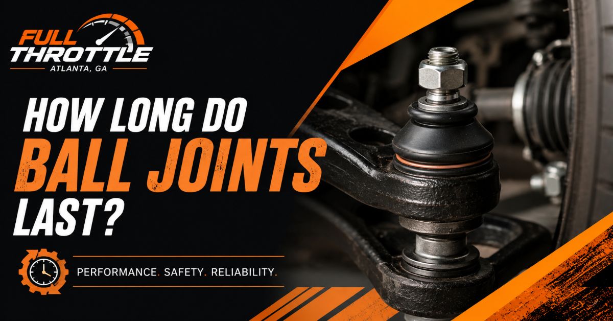
Ball joints typically last between 70,000 to 150,000 miles, influenced heavily by road conditions, driving habits, and maintenance schedules. When they fail, restoring your vehicle’s safety requires a meticulous 7-step replacement process. Taking 2 to 3.5 hours per side at a moderate DIY difficulty level, success depends entirely on proper tool handling and precision pressing techniques.
Before You Start
- Total Time: 2 to 3.5 hours per side
- Difficulty Level: Advanced DIY / Intermediate Mechanical
- Estimated Cost: $50 to $150 in parts (per side) + tool rental/purchase if needed
- Tools Required: Floor jack, 2x heavy-duty jack stands, wheel chocks, breaker bar, socket set (10mm to 24mm), needle-nose pliers, C-frame ball joint press kit with adapters, torque wrench (30-150 ft-lbs), wire brush, hammer.
- Materials Required: 1x new ball joint kit, 1 can brake cleaner, 1 can penetrating oil, chassis grease (if zerk fitting is present), 3–5 shop rags, bungee cord.
- Prerequisites: Stable concrete work surface, mechanical safety glasses, and glove protection.
Step 1: Prep and Secure the Vehicle Safely
Park the vehicle on level asphalt, engage the emergency parking brake firmly, and wedge wheel chocks securely behind both rear tires. Loosen the front wheel lug nuts by 1/2 turn using a breaker bar. Position your floor jack under the factory-designated lift point, raise the vehicle until the front wheel clears the ground, and lower it onto heavy-duty jack stands placed securely beneath the vehicle frame. Fully remove the lug nuts and pull the wheel off.
- You’ll know it worked when: The vehicle is completely stable on the jack stands with zero front-to-back or side-to-side wobble when pushed.
- Common Mistake: Working on a car supported only by a hydraulic floor jack. Always transfer the weight to solid jack stands.
Step 2: Disassemble the Brake Caliper and Rotor
Unbolt the two brake caliper mounting bracket bolts using the appropriate socket, then use a bungee cord or mechanic’s wire to hang the caliper securely from the upper frame. Slide the brake rotor straight off the wheel studs and set it aside. Unclip and disconnect the ABS wheel speed sensor wire from its mounting bracket to ensure it never stretches or snaps during suspension movement.
- You’ll know it worked when: The steering knuckle and control arm are entirely unobstructed by brake components, and the brake line shows zero tension.
- Common Mistake: Allowing the brake caliper to dangle by its rubber brake hose. This internalizes stress and causes hidden line ruptures.
Step 3: Disconnect the Ball Joint from the Knuckle
Spray all threaded fasteners and the ball joint taper thoroughly with penetrating oil and let it sit for 10 minutes. Remove the old cotter pin from the castle nut using needle-nose pliers, then loosen the castle nut until it is threaded onto the final 2 to 3 threads of the stud. Strike the side of the steering knuckle casting vigorously with a heavy hammer near the ball joint taper, or use a cup-style ball joint separator to pop the taper free. Unscrew the castle nut completely and separate the steering knuckle from the lower control arm.
- You’ll know it worked when: The ball joint stud drops free from the steering knuckle with an audible pop and moves independently.
- Common Mistake: Removing the castle nut completely before hitting the knuckle, which causes the heavy knuckle to drop suddenly and damage axle boots.
Step 4: Press Out the Old Ball Joint
Use snap-ring pliers to remove the metal retaining snap ring from the perimeter of the old ball joint if your model is equipped with one. Position the C-frame ball joint press over the control arm, placing a receiving tube larger than the ball joint body on the bottom side and a flat driving adapter on top. Turn the press forcing screw clockwise using a 1/2-inch drive breaker bar until the old ball joint is driven completely out of the control arm housing.
- You’ll know it worked when: The C-frame suddenly loses resistance and the old ball joint drops cleanly into the bottom receiving tube.
- Common Mistake: Using an air or electric impact wrench on the C-frame press. High-impact shocks strip threads instantly; always use manual hand tools.
Step 5: Clean and Prepare the Control Arm Opening
Spray the empty control arm receiving bore thoroughly with brake cleaner to flush away old grease and grit. Use a steel wire brush to scrub away rust, corrosion, and burrs inside the bore until bare metal is exposed. Wipe the interior completely dry with a clean shop rag and inspect the circular opening for cracks or oval-shaped warping.
- You’ll know it worked when: The interior ring of the control arm is clean, smooth, shiny metal with no debris or pitting left behind.
- Common Mistake: Pressing a new joint into a dirty or rusted bore, which leads to a crooked fit and premature loosening.
Step 6: Press In the New Ball Joint
Align the new ball joint perfectly straight into the clean control arm opening from the correct direction (referencing factory orientation). Reconfigure the C-frame press by placing the installation adapter flat against the new joint flange and the large receiving tube on the opposite side of the arm. Slowly turn the forcing screw by hand, checking visually from all angles that the joint enters the bore straight. Tighten until the joint flange sits 100% flush against the control arm surface, then install the new retaining snap ring into its groove using snap-ring pliers.
- You’ll know it worked when: The snap ring snaps audibly into its designated groove and you cannot slip a feeler gauge between the joint flange and control arm.
- Common Mistake: Forcing the joint in at an angle, which deforms the soft control arm metal and ruins both parts.
Step 7: Reassemble the Suspension and Torque Fasteners
Guide the steering knuckle back onto the new ball joint stud and thread the new castle nut on by hand. Use a calibrated torque wrench to tighten the castle nut to factory specifications (typically 40 to 80 ft-lbs). If the cotter pin hole does not line up with the castle nut slots, tighten the nut slightly further until it aligns. Insert the new cotter pin through the hole and bend the legs flat around the outer edges of the nut. Reinstall the ABS sensor, brake rotor, caliper bracket, and wheel, torque the lug nuts to 80–100 ft-lbs in a star pattern, and carefully lower the vehicle.
- You’ll know it worked when: All fasteners match factory torque specs, the cotter pin is secured tightly, and the wheels spin freely.
- Common Mistake: Loosening a castle nut to align the cotter pin hole. This introduces dangerous play; always tighten forward to the next window.
Common Mistakes and How to Fix Them
- Hanging Calipers by the Hose: Causes internal breakdown of the hydraulic brake line. Fix: Replace the damaged brake hose immediately if tension or bulging occurred.
- Using an Impact Wrench on the Press Tool: Strips the threads of the C-frame press. Fix: Discard the damaged press screw and use high-strength thread lubricant on a replacement kit.
- Backing Off Castle Nuts for Cotter Pins: Leaves the joint loose under driving loads. Fix: Torque the nut further to the next available slot immediately.
- Skipping Post-Installation Wheel Alignment: Results in severe, uneven tire wear and poor handling tracking. Fix: Take the vehicle to a professional alignment shop within 48 hours of replacement.
Variations: Adapting the Process to Different Scenarios
- Press-In vs. Bolted Ball Joints: Some vehicles (such as many trucks and older SUVs) feature bolt-on ball joints instead of pressed-in ones. For bolt-on types, skip Steps 4, 5, and 6 entirely; simply unbolt the old unit from the control arm and bolt the new one down, torquing mounting bolts to exact factory ratings.
- Aluminum vs. Steel Control Arms: If your vehicle uses high-end aluminum control arms, be extra cautious with hammer strikes. Striking an aluminum arm can crack the structure; use a ball joint separator tool rather than a direct hammer blow to pop the taper.
- Upper vs. Lower Ball Joints: Upper ball joints are frequently integrated directly into the upper control arm. On these models, it is often faster and safer to replace the entire upper control arm assembly rather than pressing out only the joint.
How Long Do Ball Joints Last / Cost Breakdown
Ball joint lifespans fluctuate based on environmental stress factors:
- Highway Driving / Gentle Climates: 120,000 to 150,000 miles.
- Rough Roads / Potholes / Rust Belt States: 70,000 to 90,000 miles.
- Off-Roading / Heavy Hauling: 50,000 to 70,000 miles.
- Cost Factor: Doing the job yourself costs $50–$150 in parts. Having a professional mechanic perform the replacement typically runs between $250 and $500 per side, largely driven by labor hours.
Frequently Asked Questions
How do I know if my ball joints are failing?
Common indicators include a deep clunking or popping noise when driving over bumps, a steering wheel that wanders or feels loose and unresponsive, or uneven front tire wear where the inner or outer tread is completely bald while the rest looks normal.
Can I drive with a bad ball joint?
You should never drive with a failing ball joint. If a worn ball joint completely separates while driving, the wheel will fold under the vehicle, causing an immediate, catastrophic loss of steering control and potentially a severe accident.
Should I replace ball joints in pairs?
Yes, it is best practice to replace ball joints in pairs (both front-left and front-right simultaneously). Since suspension components experience similar wear rates and road stresses, if one side has failed, the opposite side is usually near the end of its lifespan.
Do I need a wheel alignment after changing ball joints?
Yes, a professional wheel alignment is mandatory after any ball joint replacement. Disassembling the steering knuckle and control arm shifts the precise geometric angles of your front suspension, which will rapidly destroy your tires if left uncorrected.