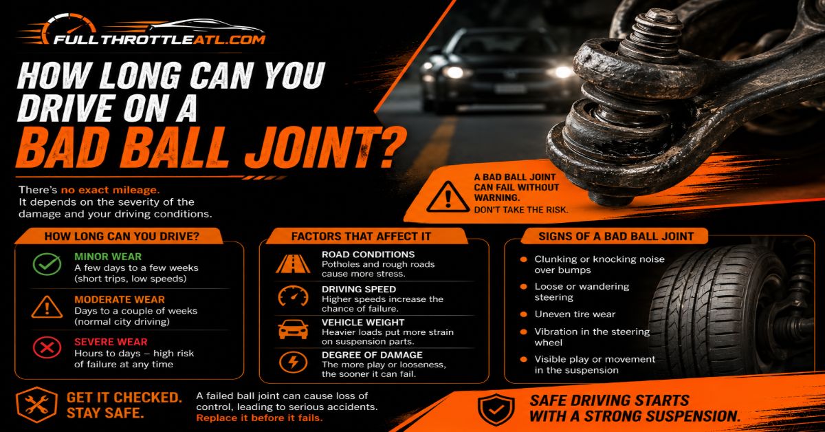
You can safely drive fewer than 500 miles only if the ball joint shows very early symptoms like minor squeaking, whereas severe play or clunking demands immediate parking. This comprehensive 8-step guide covers the entire replacement process over 3 to 4 hours at an intermediate skill level, with precision torque settings and professional failure recovery tactics ensuring permanent success.
Before You Start
- Time Required: 3.5 to 4.5 hours
- Difficulty Level: Intermediate to Advanced
- Cost Range: $60 to $150 (Parts and tool rentals)
- Tools & Materials Checklist:
- New Ball Joint Kit (OEM or high-grade aftermarket, 1 per side)
- Heavy-Duty Hydraulic Floor Jack & Jack Stands (Minimum 3-ton capacity, 1 jack, 2 stands)
- Ball Joint C-Frame Press Tool Kit with adapter sleeves (1 kit)
- ½-Inch Click Torque Wrench (30 to 150 ft-lbs range, 1 wrench)
- Impact Wrench or ½-Inch Breaker Bar (1 tool)
- Deep Socket Set & Combination Wrenches (Axle nut, lug nuts, caliper bolts, 1 set)
- Ball Joint Separator or Pickle Fork Tool (1 tool)
- Snap Ring Pliers (1 pair)
- Cotter Pins & Snap Rings (Included in new kit, 1-2 per joint)
- Penetrating Oil & Aerosol Brake Cleaner (1 can each)
- NLGI No. 2 High-Temperature Chassis Grease & Grease Gun (1 gun)
- Prerequisite Conditions: Flat, level concrete surface, wheel chocks, and basic mechanical proficiency with suspension components.
Step 1: Preparation, Vehicle Lifting, and Safety Setup
- Action: Secure the vehicle on a level surface, break the wheel lug nuts loose by one full turn, lift the front end using a 3-ton hydraulic jack, and support the chassis securely on heavy-duty jack stands.
- Execution Details: Park your vehicle on solid concrete, engage the emergency brake firmly, and wedge rubber wheel chocks tightly behind both rear tires. Use a 21mm socket or your lug wrench to crack the front wheel lug nuts loose by one single turn while the tires still touch the ground. Position your 3-ton hydraulic jack under the manufacturer-approved front subframe lift point. Raise the vehicle until the front tires clear the ground by 6 inches. Slide heavy-duty 3-ton jack stands beneath the factory pinch welds or frame rails, slowly lower the vehicle onto the stands until the weight rests securely, and give the vehicle a firm side-to-side push to verify complete stability.
- Success Check: You will know this step worked when the vehicle rests completely stationary and level on the jack stands with zero rocking or shifting motion.
- Common Mistake: Lifting the car on an asphalt driveway using a standard emergency scissor jack can cause the jack to sink into hot or soft pavement. Always use a hydraulic floor jack on flat concrete and back it up with sturdy steel jack stands.
Step 2: Wheel Removal, Fastener Prep, and Brake Component Disassembly
- Action: Remove the front wheel completely, unbolt the brake caliper and rotor, and spray all rusted suspension fasteners thoroughly with penetrating oil.
- Execution Details: Spin off the loosened lug nuts by hand and pull the wheel straight off the wheel hub studs, setting it flat underneath the vehicle frame as an added safety backup. Remove the two 15mm or 18mm bolts securing the brake caliper mounting bracket to the steering knuckle. Lift the entire brake caliper assembly off the rotor and use a bungee cord or heavy mechanic wire to hang it securely from the upper coil spring, ensuring zero tension or pulling force rests on the rubber brake hydraulic hose. Pull the brake rotor straight off the wheel hub studs and set it aside. Spray a heavy, soaking coat of penetrating oil like PB Blaster directly onto the lower ball joint castle nut, the tie rod end nut, and the steering knuckle pinch bolts. Let the chemicals soak undisturbed for 15 minutes.
- Success Check: You will know this step worked when the brake rotor is off, the caliper is safely suspended without hose strain, and all threaded fasteners are dripping wet with penetrating oil.
- Common Mistake: Allowing the brake caliper to dangle freely by its rubber flexible hose creates internal fractures in the brake line, leading to catastrophic hydraulic fluid leaks. Always hang the caliper securely.
Step 3: Outer Tie Rod Separation and CV Axle Protection
- Action: Detach the outer tie rod end from the steering knuckle using a separator tool and protect the inner CV axle shaft from over-extension.
- Execution Details: Locate the outer tie rod end connected to the steering knuckle. Remove the small cotter pin passing through the tie rod castle nut using diagonal cutting pliers. Back the castle nut off using an 18mm socket until it is flush with the very top of the threaded stud, which protects the threads from damage. Insert a mechanical tie rod separator tool or pickle fork between the tie rod arm and the steering knuckle, and strike the tail of the tool sharply with a 3-pound hand sledgehammer until the tapered stud pops upward out of the knuckle. Remove the nut entirely and push the tie rod arm out of the way. If your vehicle is front-wheel drive, slide a bungee cord underneath the lower control arm to support the inner CV axle assembly so it cannot pull outward of the transmission transaxle differential seal.
- Success Check: You will know this step worked when the tie rod swings freely away from the steering knuckle and the CV axle remains pushed fully inward toward the transmission housing.
- Common Mistake: Striking the threaded tip of the tie rod directly with a heavy hammer mushrooms the steel, destroying the threads instantly. Always strike the tool wedge or use a fork separator.
Step 4: Steering Knuckle Uncoupling from the Lower Ball Joint
- Action: Break the lower ball joint tapered stud free from the steering knuckle and separate the components without damaging surrounding boots.
- Execution Details: Remove the cotter pin from the lower ball joint castle nut. Use a 24mm breaker bar to loosen the castle nut, but leave it threaded loosely onto the final 2 or 3 threads of the stud. Insert your ball joint separator wedge tool or pickle fork between the lower control arm and the base of the steering knuckle. Strike the tool firmly with your 3-pound sledgehammer until the tightly wedged tapered stud pops loose with a loud snap. Unscrew and remove the castle nut completely. Carefully lift the steering knuckle upward and outward off the lower ball joint stud, guiding it clear while keeping the axle shaft supported.
- Success Check: You will know this step worked when the steering knuckle separates completely from the ball joint stud and swings outward with smooth articulation.
- Common Mistake: Removing the lower castle nut entirely before popping the stud can cause the heavy steering knuckle to drop abruptly, snapping wires, brake lines, or crushing fingers. Leave the nut loosely on the last threads to catch the drop.
Step 5: Old Ball Joint Removal via C-Frame Press
- Action: Set up the C-frame ball joint press tool kit with the correct adapter sleeves and force the old pressed-in ball joint out of the lower control arm.
- Execution Details: Inspect the top of the lower control arm and remove any metal retaining snap ring using heavy-duty snap ring pliers. Clean away heavy surface rust and dirt surrounding the ball joint housing using a steel wire brush. Select the correct size receiving tube (the large cup) from your C-frame press kit that matches the outer diameter of the ball joint flange. Place this receiving tube directly underneath the bottom of the lower control arm, centered squarely under the ball joint. Place the smaller driving adapter cup on top of the upper ball joint stud. Slide the C-frame press tool over the control arm so the forcing screw sits in the center of the driving cup and the bottom frame base rests under the receiving tube. Attach a ½-inch drive breaker bar or impact wrench to the forcing screw and turn it clockwise. Crank steadily until the old ball joint is forced completely downward out of the control arm bore and drops into the lower receiving tube.
- Success Check: You will know this step worked when the resistance on your wrench suddenly drops and the old ball joint falls free into the lower receiving cup.
- Common Mistake: Attempting to press out a ball joint without ensuring the receiving tube is centered flat against the control arm will wedge the joint crooked, bending the control arm or shattering the press tool frame.
Step 6: Control Arm Bore Cleaning and Inspection
- Action: Clean the interior of the lower control arm bore down to bare metal and inspect the metal edges for stretching, scoring, or cracking.
- Execution Details: Spray the empty inner circular bore of the lower control arm liberally with aerosol brake cleaner. Scrub the internal walls vigorously with a cylindrical wire tube brush to remove all baked-on rust, grit, and corrosion flakes. Wipe the inner surface clean with a shop towel until the bare metal shines uniformly. Inspect the inside edge of the bore closely under bright light. Use a digital caliper if available to verify that the internal diameter matches factory specifications and has not been wallered out or ovalized by a previously failed, loose ball joint.
- Success Check: You will know this step worked when the control arm bore is completely free of rust and scale, showing a clean, smooth, unblemished inner steel surface.
- Execution Details: Skipping the cleaning phase leaves microscopic debris inside the bore, preventing the new ball joint from seating flush and causing premature premature slippage.
Step 7: New Ball Joint Installation and Snap Ring Seating
- Action: Press the new ball joint straight into the control arm bore using the reverse press stack and instantly install the locking snap ring.
- Execution Details: Apply a very thin, uniform film of high-temperature NLGI No. 2 chassis grease around the outer metal casing of the new ball joint to ease insertion friction. Reverse your C-frame press configuration: place the large receiving tube on top of the control arm surrounding the upper bore entry, and position the flat installation adapter cup underneath the new ball joint bottom plate. Set the new ball joint squarely into the lower control arm bore, verifying with your eyes that it sits perfectly vertical and perpendicular. Crank the forcing screw clockwise with your breaker bar or impact wrench, watching the joint travel upward evenly into the bore. Continue cranking until the upper metal flange of the ball joint seats 100% flush against the bottom face of the control arm. Grab your snap ring pliers and install the new snap ring into the machined groove on the top side of the control arm, ensuring it snaps securely all the way around its circumference.
- Success Check: You will know this step worked when there is zero gap visible between the ball joint flange and the control arm, and the snap ring is fully seated in its locking groove.
- Common Mistake: Trying to tap a new ball joint into place with a hammer instead of a C-frame press will cock the joint at an angle, destroying the control arm bore and ruining the part.
Step 8: Suspension Reassembly and Precision Torquing
- Action: Reconnect the steering knuckle to the new ball joint, reassemble the brakes and tie rod, and torque all fasteners to exact factory specifications.
- Execution Details: Lift the steering knuckle and guide the new tapered ball joint stud straight up into the knuckle mounting hole. Hand-thread the new castle nut onto the stud threads. If the tapered stud spins freely inside the knuckle hole when you turn the nut, place a floor jack beneath the lower control arm and jack it upward slightly to put weight on the stud and lock the taper. Use your ½-inch click torque wrench to tighten the ball joint castle nut to your vehicle’s exact factory specification (typically between 50 and 80 ft-lbs). Inspect the cotter pin hole: if the hole does not align with the castle nut slots, tighten the nut slightly further until it matches—never loosen it. Insert a new cotter pin through the hole and bend the legs outward around the nut. Reinstall the brake rotor, mount the brake caliper bracket, torque bracket bolts to 75–100 ft-lbs, reconnect the outer tie rod and torque its nut, reinstall the front wheel, lower the vehicle to the ground, and torque the lug nuts in a star pattern to 80–100 ft-lbs.
- Success Check: You will know this step worked when all suspension fasteners match factory torque specs, cotter pins are locked securely, and the wheel spins freely without brake drag.
- Common Mistake: Backing a castle nut up to align a cotter pin hole reduces clamping preload, which lets the nut vibrate loose while driving and separates the suspension. Always tighten forward to align.
Common Mistakes and How to Fix Them
- New Joint Stud Spins Freely While Torquing: The internal taper is not wedged tight enough inside the steering knuckle. Fix: Place a hydraulic floor jack directly under the lower control arm and raise it to force the vehicle weight into the joint taper, stopping the spin instantly.
- Forcing a Crooked Ball Joint Press: The press adapter slipped during pressing, cocking the joint sideways. Fix: Stop immediately, press the joint back out, inspect the bore for scoring, and restart with the press components perfectly square.
- Forgetting the Snap Ring: The joint is pressed in, but the snap ring was left off the top groove. Fix: Lift the vehicle, support the control arm, clean the top groove, and install the snap ring immediately before driving, otherwise the joint can unseat under load.
- Skipping Wheel Alignment After Repair: Replacing a ball joint shifts static suspension geometry parameters. Fix: Drive directly to an alignment shop or book a professional 4-wheel alignment within 48 hours to prevent destroying expensive tires.
Variations: Adapting the Process
- Bolt-In vs. Pressed-In Ball Joints: Some trucks and utility vehicles feature bolt-in ball joints secured by 3 or 4 heavy fasteners rather than a press fit. For bolt-in units, skip the C-frame press entirely, remove the mounting bolts using a socket wrench, drop the old joint out, and bolt the new unit straight in, torquing fasteners to spec.
- Upper Control Arm Ball Joints: If you are replacing an upper ball joint on a short-long arm suspension setup, you typically must unbolt the entire upper control arm from the inner chassis frame or separate the upper ball joint stud from the top of the knuckle. Support the lower control arm with a jack stand to relieve spring tension if a coil spring pushes against the upper arm.
How Long Does It Take / What Does It Cost
- Time Investment: A professional mechanic takes about 1.5 to 2 hours per side, while a first-time DIYer working at home should budget 3.5 to 4.5 hours for a single side, accounting for stubborn rusted fasteners and tool setup.
- Financial Cost: Doing the job yourself costs between $40 and $100 for a quality aftermarket ball joint kit, plus about $20 in consumables like brake cleaner and grease. Professional shop replacement typically ranges from $250 to $600 per side including labor and parts, plus a mandatory $100 alignment fee.
Frequently Asked Questions
Can I drive with a squeaking ball joint?
You can drive short distances to a repair shop if the squeak is faint and intermittent, but it signals that the internal grease boot has failed and metal-on-metal friction has begun. Inspect the boot immediately for tears and schedule replacement before the joint develops play or catastrophic failure.
Do I need to replace ball joints in pairs?
Replacing ball joints in pairs (both driver and passenger sides) is recommended if your vehicle has high mileage, because wear rates across front suspension components are usually identical. If one side fails due to a torn boot while the other side is relatively new and tight, replacing only the failed side is acceptable.
How do I know if my ball joint is bad before starting?
Common symptoms of a bad ball joint include a loud rhythmic clunking noise when driving over bumps, a loose or wandering steering wheel that pulls to one side, uneven tire wear on the inner or outer tread edges, and visible wheel play when jacking up the car and rocking the tire at the 12-o-clock and 6-o-clock positions.
Can a bad ball joint cause a blowout?
A bad ball joint will not directly puncture your tire, but if the ball joint separates completely while driving, the steering knuckle detaches from the lower control arm. This causes the wheel to collapse outward, forcing the tire to rub violently against the inner fender well or shred itself against structural metal components.